Saturday, 1 December 2012

How heavy is the tender?

The short answer is around 36 tons when empty.  But it is important that the weight is evenly distributed around the six wheels so that the tender rides properly behind the locomotive (or sometimes in front of it).  To achieve this, the weight on each wheel has to be measured, and adjustments made to give an even distribution. Fortunately there is a device that is owned by the railway that allows us to make this measurement.

The device consists of a frame with two hydraulic pistons attached.  The pistons are connected by pipes to a hydraulic pump.  With the tender positioned over a pit, the frame is placed under each wheel in turn.  Due to the magic of hydraulics, the device allows a person to operate the pump by hand and produce enough force to lift the tender wheel.  The pressure is then read from a gauge on the pump.


Gilbert operating the hydraulic pump


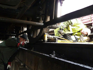
This is a two man job.  One person operates the pump, while a second person is down in the pit below the tender.  While the pump is operated, the person in the pit uses feeler gauges to determine when the wheel has just started to lift from the track.  The pressure is recorded, and the processs is repeated for the other five wheels.


Geof in the pit checks for the wheel to lift


With readings from each wheel it can be determined whether the weights are even, and if not the spring hangers can be adjusted to alter the weight on the wheel.  Frequently adjusting the weight on one wheel will change the weight on the others.  The weighing, adjusting, weighing, adjusting process is repeated until all of the wheels are even.  This can take some time!


Monday, 19 November 2012

Looking for trouble

We're a daft lot, those of us who volunteer to maintain steam locos. You quickly learn that complaining about things going wrong is waste of breath and simply invites comments such as " Ha, ha, that's steam locos for you!" and others less printable. But it is all done in good humour and when the chips are down most everyone will muck in and help you get the problem sorted. And it can be very mucky work!

A good starting point is that "if nothing looks wrong then you're not looking hard enough" closely followed by "if something can go wrong then it will sooner or later" With that in mind and having a few weeks before the loco is needed for Santa Specials duty, I asked the question "When was the last time we looked the tender axle boxes?" "Er, not recently" was eventually tracked down to mean not since the tender had come back from restoration work at Tyseley - 20 years ago. "Ah" I said and set off for some spanners hoping for inspiration about exactly how one strips down a tender axle box and thinking it couldn't be too different from doing the driving wheel axle boxes which I had done before.

So to work, with the blind (Gilbert) leading the blind (me!) or maybe it was the other way round. Starting with what we knew, we removed the LHS leading axle box cover to expose the brass plate that is white metaled on the face sitting on the axle journal. We inserted 2 bolts into the holes at the end of the plate to draw it out later when had removed the underkeep and lowered the axle Then we removed the nuts on the underkeep bolts.  At which point the bolts should be turned lifted and the underkeep withdrawn.  3 behaved perfectly. The 4th just would not be lifted - typical. After quite a few failed attempts and a cuppa we resorted to plan B.  Remove the horn guide tie bar below the underkeep and lower the underkeep from its retaining bolts. Easy job.


Next we replaced the tie bar and made a couple of spacers to hold the axle box in place relative to the tie bar.  Then we jacked up the end of the tender to allow the axle to drop and free the brass  to the point where it could be with drawn through the hole where the cover plate had been removed. Success comes those who persevere!

The white metaling on the brass was found to be in excellent condition.  So we got out the new steam pressure washer  and cleaned the brass and the axle box underkeep. The brass went in easily enough. Fitting the underkeep should have been straightforward enough except the bolts kept turning and dropping off the locating lugs in the axle boxes as we tried to turn the nuts at the end of the bolts.   It was one of those jobs best done by an octopus; we needed more hands. Fortunately Fred turned up in the nick of time and although protesting that he had just cleaned his hands, he saved the day and the battle was won. Job was soon wrapped up after that. SO just another 5 to do...only another 30 hours of work then!

Wednesday, 14 November 2012

Maintenance Progress

Bruce, Steve and Howard continued work painting areas of the tender with bitumastic paint.

A coat of bituminastic paint was applied to the rear deck area of the tender and the area under the footplate.  A second coat was applied to the coal space.

Geof and Gilbert continued with the tender axleboxes.

Saturday, 10 November 2012

Maintenance Progress

Bruce, Steve and Ingo painted the tender coal space with bitumastic paint.

The coal space was brushed down and vacuumed to remove all loose debris. This area was painted while the drawbox and footplate areas were cleaned.

The back deck was cleared of wood and debris. Localised patches of damp were cleaned up and dried with the hot air gun. Loose and cracked paint was wirebrushed and chipped as appropriate. The entire deck area was vacuumed to remove loose debris.
 
  
Tender Coal Space
Tender Coal Space
 
By the end of the day the entire coal space had received one coat of bitumastic paint and requires at least 24 hours drying time before a second coat is applied. The rear deck and under the footplate are ready to start painting.

Meanwhile Gilbert and Geof were working on the tender axleboxes. See later post on this blog.